The Hidden Danger of Drone Arm Deflection
When designing heavy-lift multirotors or agricultural drones, structural rigidity is just as important as weight reduction. A common mistake we see in UAV design is underestimating the dynamic forces applied to the motor mounts. When drone arm deflection occurs under heavy payload or aggressive maneuvers, it creates severe aerodynamic and software complications.
Excessive flex alters the thrust vector of your motors. If a boom bends upward by just a few degrees under full throttle, the thrust is no longer directed straight down. This forces the flight controller to work overtime, leading to overcompensation and oscillating PID loops. The result is a sluggish, vibrating drone that consumes battery rapidly.
Furthermore, repeated calculating carbon tube bending cycles lead to material fatigue. While carbon fiber has incredible tensile strength, improper layup schedules combined with high cyclical loading can eventually cause matrix micro-cracking. Predicting and eliminating this flex in the design phase is non-negotiable for professional UAVs.
The Core Formula for Carbon Fiber Tube Deflection Calculation
To predict how much a carbon fiber tube will bend, we treat the UAV boom as a cantilever beam. A cantilever beam is rigidly fixed at one end (the central frame) and subjected to a point load at the free end (the motor and propeller thrust).
The standard engineering formula for maximum deflection at the free end is:
$$\delta=\frac{F \cdot L^3}{3 \cdot E \cdot I}$$
Here is a breakdown of the variables in this equation:
- $\delta$ (Deflection): The total displacement at the end of the tube, measured in meters (m) or millimeters (mm).
- $F$ (Force): The load applied at the end of the boom, measured in Newtons (N). This is your motor’s maximum thrust.
- $L$ (Length): The active length of the tube from the frame clamp to the motor mount, measured in meters (m).
- $E$ (Modulus of Elasticity): The stiffness of the composite material, measured in Pascals (Pa) or Gigapascals (GPa).
- $I$ (Area Moment of Inertia): A geometric property of the tube’s cross-section, measured in meters to the fourth power ($m^4$).
Calculating the Area Moment of Inertia (I)
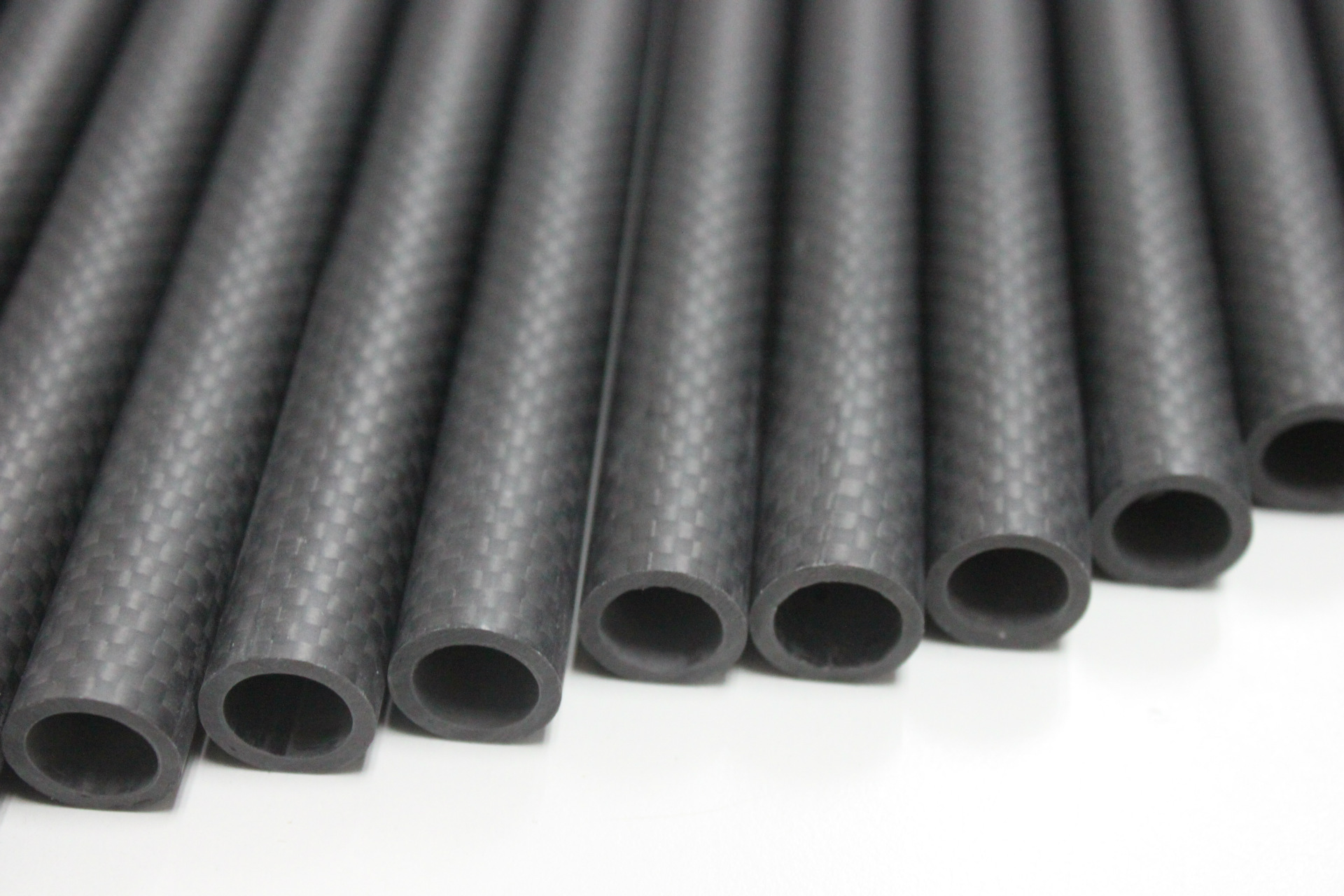
Because most UAV booms utilize hollow circular profiles to save weight, calculating the area moment of inertia requires both the outer diameter ($D$) and inner diameter ($d$).
The formula for a hollow cylinder is:
$$I=\frac{\pi}{64}(D^4-d^4)$$
Maximizing the outer diameter while maintaining a thin wall is geometrically the most efficient way to increase $I$, which drastically improves UAV boom stiffness without adding significant mass.
Understanding the Modulus of Elasticity for Carbon Fiber
Unlike isotropic metals such as aluminum, carbon fiber composites are highly anisotropic. Their stiffness depends entirely on the fiber type and the orientation of the layers (ply schedule). You cannot simply use a generic value for carbon fiber.
For standard roll-wrapped tubes where the majority of fibers run at 0 degrees (longitudinally), the modulus of elasticity for carbon fiber typically ranges from 100 GPa to 130 GPa. If you upgrade to High Modulus (HM) or Ultra-High Modulus (UHM) prepreg materials, the effective $E$ value can exceed 250 GPa.
If your structural calculations indicate excessive deflection, you can easily swap standard tubes for our specialized custom carbon fiber tubes engineered with pitch-based fibers to double the stiffness without altering your drone’s geometry.
Step-by-Step Calculation Example
Let’s walk through a practical example for a commercial quadcopter. We want to determine if our chosen tube will flex too much under a heavy payload.
The Design Parameters:
- Boom Length ($L$): 400 mm (0.4 m)
- Outer Diameter ($D$): 25 mm (0.025 m)
- Inner Diameter ($d$): 23 mm (0.023 m)
- Max Thrust Force ($F$): 80 N (approx. 8 kg of thrust per motor)
- Material Modulus ($E$): 115 GPa ($115 \times 10^9 \text{ Pa}$)
Step 1: Calculate $I$
$$I = \frac{\pi}{64}(0.025^4 – 0.023^4)$$
$$I = 5.45 \times 10^{-9} \text{ m}^4$$
Step 2: Calculate Deflection ($\delta$)
$$\delta = \frac{80 \cdot 0.4^3}{3 \cdot (115 \times 10^9) \cdot (5.45 \times 10^{-9})}$$
$$\delta = 0.00272 \text{ m}$$
In this scenario, the drone arm deflection is roughly 2.72 mm under absolute maximum load. For most mid-sized commercial drones, less than 3 mm of deflection at full throttle is an acceptable margin for stable flight.
Nexrik’s Approach to High-Modulus Carbon Tubes
At Nexrik, we don’t just supply tubes; we engineer structural solutions. By controlling the resin fraction and utilizing advanced prepreg roll-wrapping techniques, we achieve an optimal composite density of ~1.55 g/cm³.
Our manufacturing processes comply strictly with ISO 9001:2015 standards, ensuring that every tube batch maintains consistent tensile strength exceeding 1500 MPa. We balance hoop strength with longitudinal stiffness so your booms resist crushing forces from frame clamps while remaining perfectly rigid in flight.
Whether you are designing multirotors, fixed-wing VTOLs, or robotic arms, pairing our high-modulus tubes with our CNC machined carbon fiber plates creates an ultra-rigid airframe chassis that maximizes payload capacity and flight time.
Conclusion
Calculating carbon fiber tube deflection is a fundamental step in aerospace design that cannot be overlooked. By understanding the relationship between applied force, tube geometry, and material stiffness, you can eliminate flight instability before a prototype ever leaves the ground.
If your current frame design is experiencing too much flex, our engineers can help you spec the exact ply schedule and fiber grade needed to solve the problem. Contact our technical team today to Request an Engineering Quote.
TL;DR: Accurate carbon fiber tube deflection calculation is critical for maintaining UAV boom stiffness and preventing flight instability. To calculate deflection, you must determine the applied load, boom length, area moment of inertia, and the specific modulus of elasticity for carbon fiber. Using a standard cantilever beam formula, engineers can predict exactly how much a drone arm will bend under maximum thrust. At Nexrik, our engineering team manufactures ISO 9001:2015 certified carbon fiber components tailored for zero-flex aerospace applications.
Discuss Your Specific Requirements
Stop guessing with standard tolerances. Let our engineering team review your CAD files for actionable DFM feedback.
Request Engineering Review